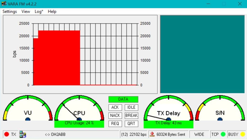
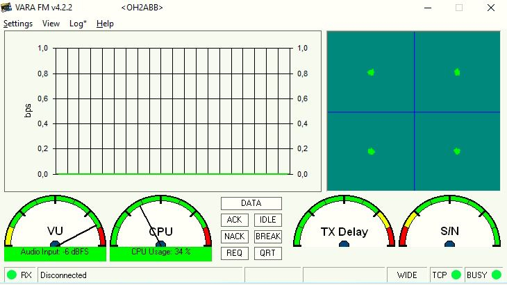
Motorolan 128 kanavaiset GM sarjan radiot soveltuvat hyvin VARA FM siirtoon filtteröimättömän audion ulostulon ja sisääntulon ansiosta. Maksimi 25,210 bps ei ole este motorolille. Pullonkaulaksi tulee äänikortti ennemmin kuin radio.
Hyväksi todettuja radioita ovat :
GM350 128 kanavaa
GM950 128 kanavaa
CM340 10 kanavaa
4 kanavainen GM350 esimerkiksi ei sovi datakäyttöön.
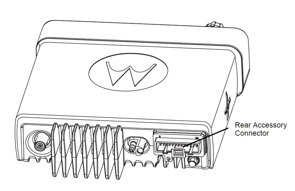
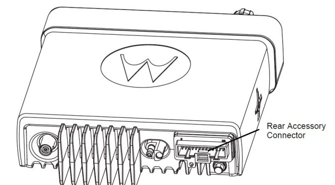
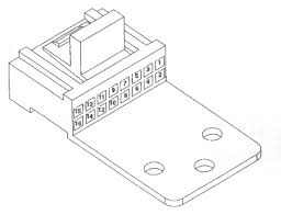
16- pinninen Accessory liitin 4 ja 128 kanavaisissa radioissa :
| Pin | Name | Type | 4-Channel | 128- Channel |
| 1 | SPKR- | Analogue Output | x | x |
| 2 | Ext Mic Audio | Analogue Input | x | x |
| 3 | GP1 | Digital Input | x | x |
| 4 | GP2 | Digital Output | x | |
| 5 | Flat Tx Audio | Analogue Input | x | |
| 6 | BUS+ | Digital i/o | x | x |
| 7 | GND | GND | x | x |
| 8 | GP3 | Digital i/o | x | |
| 9 | GP4 | Digital ip capture | x | |
| 10 | Ignition Sense | Digital Input | x | x |
| 11 | Rx Audio | Analogue Output | x | |
| 12 | GP5 | Digital i/o | x | |
| 13** | SW B+/GND | Analogue output | x | |
| 14 | GP6 | Digital i/o | x | |
| 15 | RSSI | Analogue Output | x | x |
| 16 | SPKR+ | Analogue Output | x | x |
Pin 1. – Speaker – audio
Speaker – and Speaker + (Pin 16) are used to connect an external speaker. The audio PA is a bridge amplifier with a minimum load resistance of 3.2 ohms. The internal speaker can be disabled by removing the control head. Disconnect the internal speaker and assemble the control head back to the radio.
Pin 2. – Microphone audio
This microphone signal input is common with the microphone signal input on the microphone connector and is connected to the rtiicrophone path input of the AFIC. The nominal input level is 80mV for 60% deviation. The DC impedance is 1100 ohms and the AC impedance is 1000 ohms Note: Only one microphone should be connected at any one time.
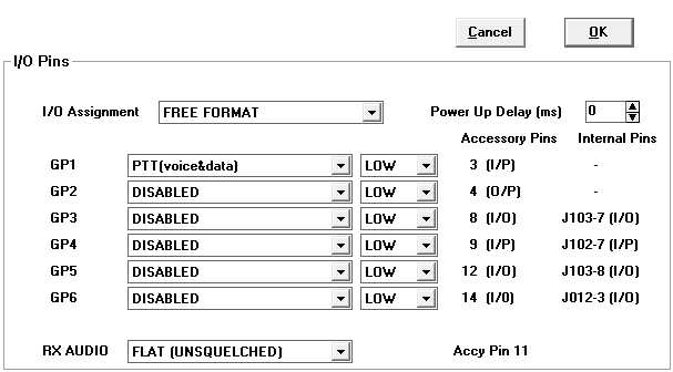
Pin 3. – General Purpose 1 (GP 1)
This is a digital input only. The RSS details which functions may be assigned to this pin by the codeplug. The primary use for this pin will be external PTT. (See Note 1).
Pin 4. – General purpose 2 (GP2)
This is a digital output only The RSS details which functions may be assigned to this pin by the codeplug. The primary use for this pin is as external alarm output.
Pin 5. – Flat TX audio
This input is for injecting signals into the transmit path that should not be filtered, e.g. the output of a modem. The nominal input level is l5OmVRMS for 60% deviation. The impedance is greater than 25kohms.
Pin 6. – BUS+
This connects to the radio’s SCI serial bus which is used for programming and tuning the radio. The line is also available at the microphone connector Pin 7.
Pin 7. – Ground
Used as ground for both analogue and digital signals.
Pin B. – General purpose 3 (GP3)
This is a digital input/output and is also available on the internal option connector (JOl 03:7). The RSS details which functions may be assigned to this pin by the codeplug.
Pin 9. – General purpose 4 (GP4)
This is a digital input only. It is also available on the internal option connector (JO102:7) and is used in input capture mode when a serial type option board is fitted. The RSS details which functions may be assigned to this pin by the codeplug.
Pin 10.- ignition sense
Connecting this line to the ignition line of the vehicle will automatically turn the radio on when the ignition of the vehicle is turned on. When ignition is connected, the radio cannot be turned off as long as the ignition is active. When this line is at OV or not connected, power on/off is under manual control. Resistor R0423, 4.7ki2, which is not fifted as standard will cause the radio to be permanently on whenever 12V is connected to the main power connector.
Pin I I.- RX Audio Discriminator/Filtered (Analogue output)
The signal routed to this pin is controlled by AFIC. There are two possible outputs; continuous discriminator audio or continuous filtered RX audio output of AFIC. The output mode can be selected by the RSS, however, this mode may be overridden during certain tuning operations. For discriminator audio, the nominal ouput level is 330mVRMS for 60% deviation. The impedance is 600ohms. For filtered audio, the nominal ouput level is 600mV for 60% deviation. The impedance is 600ohms.
Pin 12.- General purpose 5 (GP5)
This is a digital input/output and is also available on the internal option connector (JOl 03:8). The RSS details which functions may be assigned to this pin by the codeplug.
Pin 13.- Switched B+ / Analogue Ground
The output of this pin may be configured by a solder link within the radio. Switched B+ is the default. The current limiting resistor (RO455) default is O ohm, therefore extreme care must be taken to avoid short circuiting this output to ground, which will damage the radio.
CAUTION:The maximum continuous current allowed is 3OOmA. A suitable external fuse must be installed into the lead to pin 13 to avoid damage to the radio.
Pin 14.- General purpose 6 (GP6)
This is a digital input output and is also available on the internal option connector (J0102:3). The RSS details which functions may be assigned to this pin by the codeplug.
Pin 15.- RSSI
Received Signal Strength Indication, buffered analogue voltage.
Pin 16.- Speaker+ audio
Positive output of radio’s audio PA (see Pin 1).
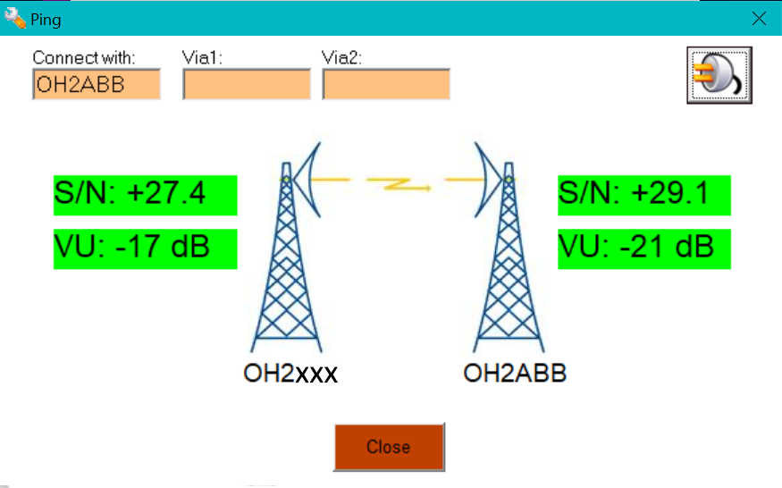
Olemme testanneet signalink USB:tä ja DRA-50:tä Motorola GM350 ja GM950 kanssa ja kummallakin olemme päässeet korkeimpaan nopeuteen mitä VARA FM voi siirtää eli 25,210 bps. Signalinkeissä joissa on punaiset muuntajat ei pitäisi päästä korkeimpaan nopeuteen, mutta kyllä pääsee!
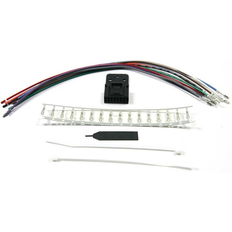
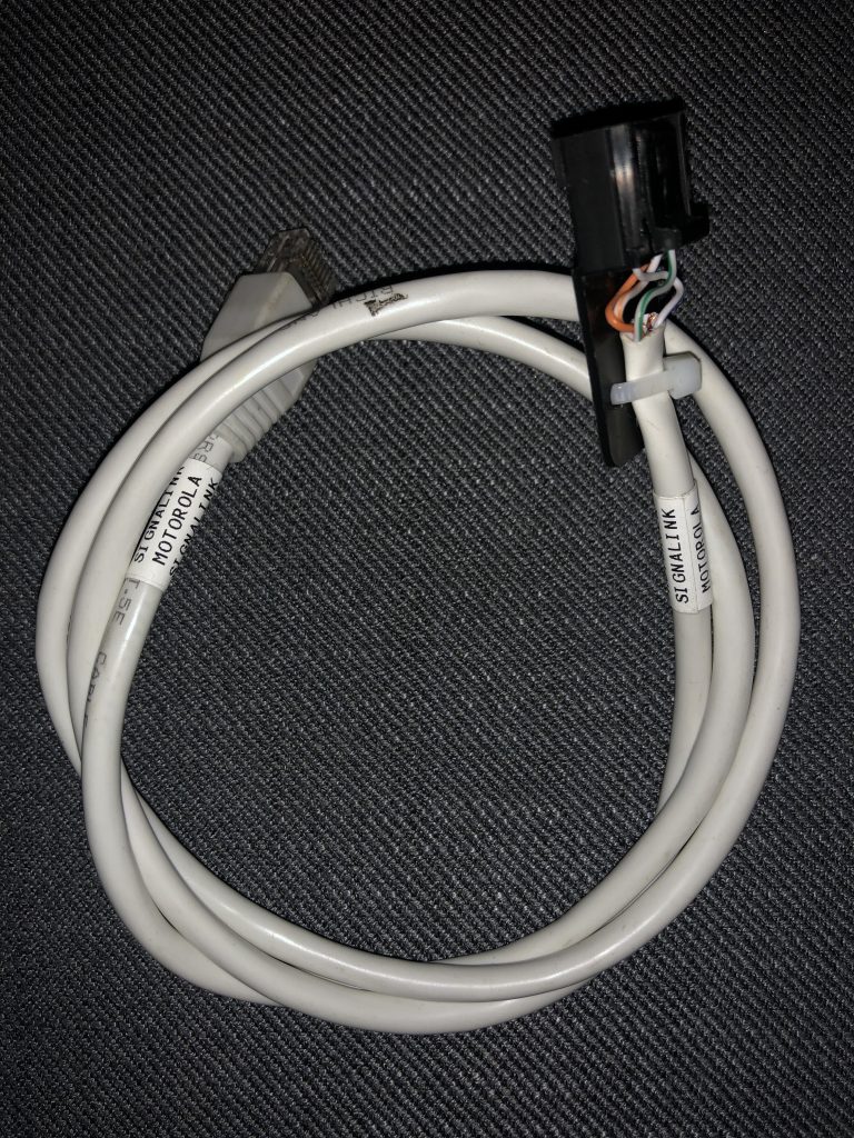
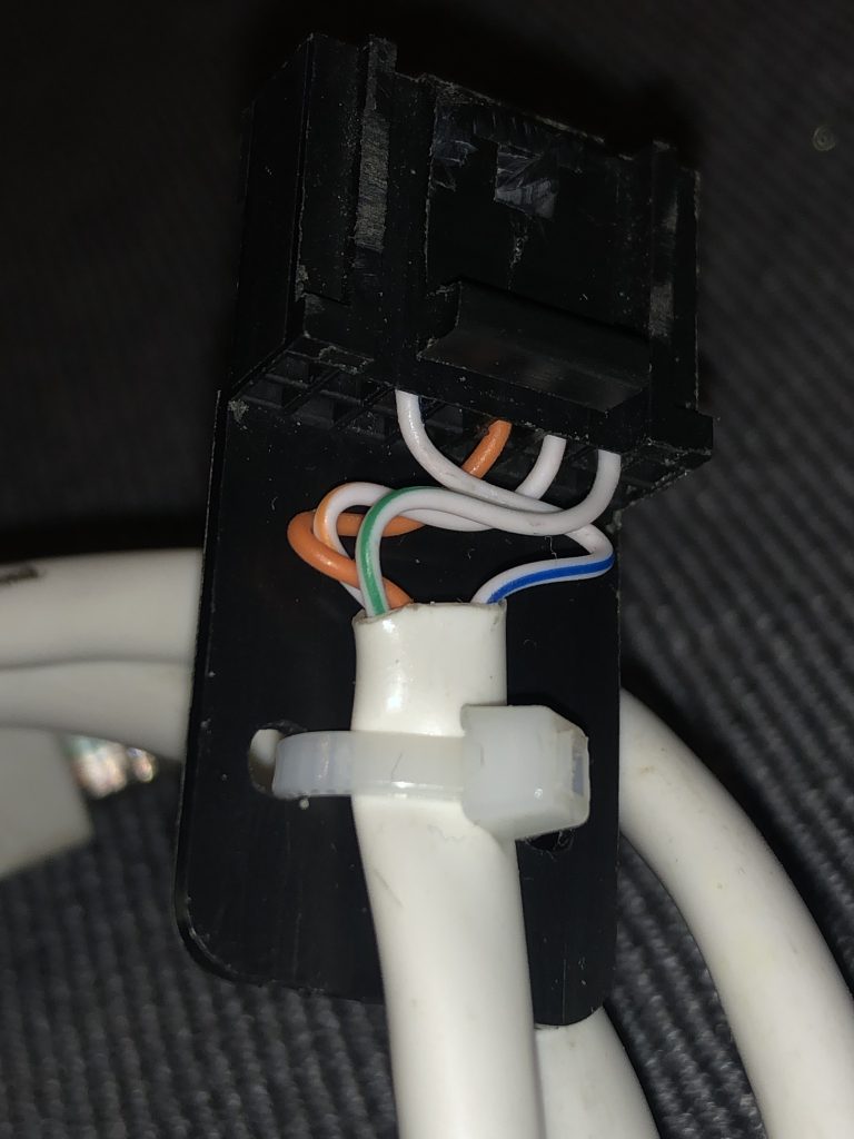
Signalinkkiin on jumpperoitava radio kohtaisesti pinnijärjestys, mutta itsetehdyissä kaapeleissa voi järjestyksen kääntää kaapelissa, eli vaikka Yaesulle jumpperoitu Signalink käy Motorolaan jos kaapelin tekee itse.